In the learning process of the analog circuit, it is necessary to have the ability to recognize the circuit diagram. However, it is difficult to master in a short period of time. This article will introduce the characteristics and structure of the voltage regulator circuit in the circuit diagram. It is easier for beginners to understand by dividing the circuit diagram.
Regulator circuitFluctuations in the AC grid voltage and changes in the load current cause the output voltage and current of the rectified power supply to fluctuate accordingly. Therefore, a higher power electronic circuit must use a regulated power supply.
Zener diode shunt regulator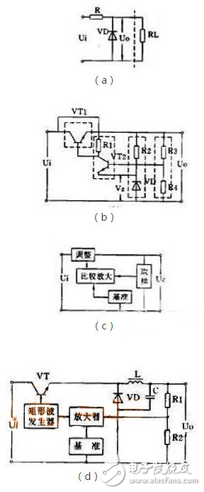
A circuit with a Zener and a load in parallel is the simplest regulator circuit, see Figure 1(a). In the figure, R is a current limiting resistor. The output current of this circuit is very small, and its output voltage is equal to the stable voltage value VZ of the Zener diode.
Series regulator circuitA series regulator circuit with amplification and negative feedback is the most commonly used regulator circuit. Its circuit and block diagram are shown in Figures 1(b) and (c). It detects the change of the output voltage from the sampling circuit (R3, R4), compares it with the reference voltage (VZ) and amplifies it by the amplifier (VT2) and applies it to the adjusting tube (VT1) so that the voltage across the adjusting tube follows Variety. If the output voltage drops, the voltage drop of the adjustment tube is also lowered, and the output voltage is raised. If the output voltage rises, the voltage drop of the adjustment tube is also increased, so that the output voltage is depressed, and the output voltage is substantially unchanged. . On the basis of this circuit, it has developed into many variant circuits or added some auxiliary circuits, such as a composite tube as an adjustment tube, an output voltage adjustable circuit, an operational amplifier for comparative amplification, and an auxiliary power supply and overcurrent protection circuit. Wait.
Switching regulator circuitThe new regulated power supply widely used in recent years is a switching regulator power supply. Its adjustment tube works in the switching state, its own power consumption is very small, so it has the advantages of high efficiency, small size, etc., but the circuit is more complicated.
There are many different types of switching regulators. Its basic principle block diagram is shown in Figure 1(d). In the figure, the inductor L and the capacitor C are energy storage and filter components, and the diode VD is a freewheeling diode that provides a current path for the L and C filters when the switch is in the off state. The switching frequency of the switching power supply is very high, generally several to several tens of kilohertz, so the volume of the inductor is not large, and there are not many high harmonics in the output voltage.
Its basic working principle is: detecting the sampling voltage from the sampling circuit (R3, R4) and comparing it to a rectangular wave generator. The output pulse of the rectangular wave generator controls the conduction and cut-off time of the regulating tube (VT). If the output voltage U0 is lowered due to fluctuations in the grid voltage or load current, the output pulse of the rectangular wave generator is widened, so that the conduction time of the adjustment tube is increased, so that the L and C tank circuits obtain more energy. As a result, the output voltage U0 is boosted to achieve a stable output voltage.
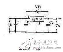
Integrated voltage regulator circuitIn recent years, a large number of integrated voltage regulator products have been introduced, with many varieties and different structures. At present, there are three-terminal integrated voltage regulators, such as the CW7800 series that output positive voltage and the CW7900 series that output negative voltage. The output current is from 0.1A to 3A, and the output voltage is 5V, 6V, 9V, 12V, 15V, 18V, 24V, etc.
This integrated regulator has only three terminals, and all parts of the regulator circuit, including the high-power adjustment tube and protection circuit, are integrated into the chip. When you use it, just add the heat sink and connect it to the rectifier filter circuit. There are few external components, high voltage regulation accuracy, reliable operation, and generally no debugging is required.
Figure 1(e) shows a three-terminal regulator circuit. In the figure, C is the main filter capacitor, C1 and C2 are capacitors for eliminating parasitic oscillations, and VD is a protection diode used to prevent the input short circuit from burning out the integrated block.
As can be seen from the above description, the voltage regulator circuits in the circuit are basically divided into four types. As long as you master these four circuit types, it is very easy to identify the voltage regulator circuit in the circuit diagram. The more types of circuits that can be identified, the more accurate and fast the interpretation of the circuit. I hope everyone will gain something after reading this article.
AC Power Adapter,Power Adapter,USB Power Adapter,Electrical Power Adapters
Dongguan baiyou electronic co.,ltd , https://www.dgbaiyou.com