Methods for measuring the grounding resistance include voltage, ammeter, and dedicated grounding resistance.
First, voltage, current meter method

The function of the isolation transformer in Figure 14-1 is to isolate the Power Supply to ground (that is, directly form a loop without ground). This is because the general low-voltage AC power supply is composed of one phase, and if there is no isolation transformer, the phase line The terminal directly connected to the grounding device under test may cause a short circuit similar to the voltage regulator, and the test current to be tested is large. The transformer can be a 6-10kV distribution transformer used independently. The low voltage side 400V is applied between the grounding grid and the current pole to form a current of several tens of amperes. An AC welding machine can also be used. The current and voltage poles can be made of angle steel or steel pipe, the buried depth should be greater than 0.8m, and the cross-sectional area of ​​the wire should be greater than 1.5mm2. The current pole and the ground electrode to be tested form a current loop; the voltage pole is used to obtain the potential of the side grounded body. When a power frequency voltage is applied between the current pole and the ground grid, the power frequency current I passes through the grounding resistance of the grounding grid. , using the voltmeter to measure the voltage drop U of the current I on the grounding resistance between 1, 2 and 2 points, then the grounding resistance Re value is calculated as
Re=U/I
The test should be carried out in dry weather, and should be repeated 3 to 4 times and averaged.
For the power plant and substation grounding network in operation, if there is interference current flowing in the ground and the voltmeter reading also contains the interference voltage, the measurement result is not the actual grounding resistance value. At this time, the power supply can be inverted (see Figure 14). -2) or increase the test current to eliminate and reduce the error caused by interference. For the case where the current and voltage measurement lines are long and parallel, the mutual inductance voltage formed by the mutual inductance between the lines will also affect the measurement result. At this time, the power table method (see Figure 14-3) can be used to measure the grounding resistance. At this time, R e = P/I 2 = U 2 /P; P = (P z + P f )/2. Where PZ is the measured power (W) when the power supply is positively pressurized; Pf is the measured power (W) when the power supply is reversely pressurized.

The steps to measure the grounding resistance using the inverting method are as follows:
(1) Disconnect the power switch and short-circuit the isolation transformer on the primary side, the interference current and voltage.
(2) Measure current and voltage at forward voltage.
(3) Measure current and voltage at reverse voltage.
The test poles are arranged in two ways, the straight line method and the angled angle method, as shown in Figure 14-4 when there is no power supply.

When using the straight line method, as shown in Figure 14-4 (a), the distance d13 between the current pole and the edge of the grounding body is generally 4 to 5 times the maximum diagonal length D of the grounding body, d12: 0.618d13 . In case of difficulty, D13=2D and D12=1.3D in areas with uniform soil resistivity; d13=3D and d12=1.7D in areas with uneven soil resistivity.
When measuring, move the voltage pole three times along the connection direction of the grounding body and the current pole. Each moving distance is about 5% of d13. The difference of the grounding resistance value measured three times should be less than 5%. Otherwise, it should be ascertained. The reason is, for example, whether the current and voltage pole leads are too short. Take the average of 3 times as the grounding resistance of the grounding body.
When using the angle method, as shown in Figure 14-4 (b), generally take d12 = d13 ≥ 2D, the angle α ≈ 30 °, the voltage should be moved back and forth three times before the measurement, take the average of 3 times value.
The angle method has the following advantages compared with the straight line method:
(1) The influence of mutual inductance between leads can be reduced.
(2) In the uneven soil, when d13=2D is taken, the result measured by the angle method is equivalent to the measurement result of the straight line method d13=3D.
(3) The potential change near the voltage pole of the angle method is gentle, and the potential change from 29° to 60° corresponds to the potential change of 0.618d13 to 0.5d13 of the straight line method. Therefore, due to the positional deviation of the angle method, the angle between the voltage pole and the current pole to the grounding body is not accurate, and the soil resistivity is not uniform, resulting in an error caused by irregular potential distribution, generally smaller than the straight line method. .
Second, the grounding resistance measuring instrument measurement method
There are many types of grounding resistance measuring instruments, which are usually measured by a domestic ZC-8 type grounding resistance meter. The working principle and measurement method of the measuring instrument are briefly described below.

Figure 14-5 shows the principle wiring of the ZC-8 type grounding resistance meter. The meter is mainly composed of a hand crank generator, a current transformer, an adjustable resistor Rs and a galvanometer. Connect the terminal "E" to the ground electrode to be tested, "C" to the current pole, and "P" to the voltage pole. Shaking the generator handle, current I1 is returned to the generator from the generator through current transformer TA, grounding pole E, earth and C. The current I2 is a secondary current induced by the current transformer, and the loop is formed by the adjustable resistor Rs. Adjust the contact "B" of Rs to zero the galvanometer. Then the potential difference between E and P is equal to the potential difference between point O and point B of Rs . If the scale is full scale 10 and the reading is N, then the following equation is obtained.
I1*Rx=I2*RsN/10; Rx=I2/I1*R5*N/10
The proportional relationship between I1 and I2 can be changed by the override switch S so that three different ranges can be obtained. The meter has 0~1/10/100Ω and 0~10/100/1000Ω (two measurement ranges for use).
When measuring the grounding resistance, you should pay attention to the following problems:
(1) It should be carried out in dry weather, avoiding the rain immediately, and recording the weather conditions during the measurement.
(2) The cross-sectional area of ​​the test leads used shall not be less than 1~1.5mm2; the test leads shall be insulated from the ground. When measured with a zc8 type meter, the resistance of the test leads should not be greater than 2% to 3% of Rx.
(3) The leads of the current and voltage poles should be in the vertical direction of the line or underground metal pipe.
(4) In order to reduce the measurement error, when the ground point to be tested is painted or rusted, it should be removed before measurement.
(5) When measuring, the grounding device to be tested should be disconnected from the lightning protection line.
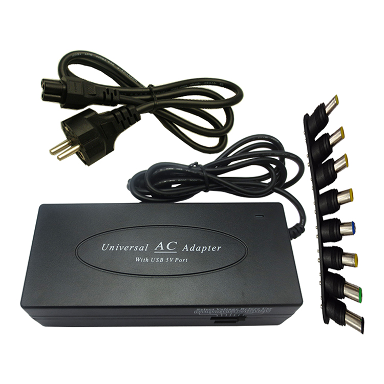
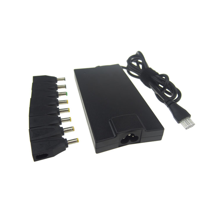
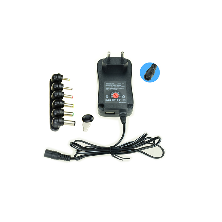
If you are desperately looking for a safe, portable power charger for different brands laptop, spare or for travel with multiple devices, this is the one for you--universal Laptop Charger.
Yidashun offer manual and automatic universal laptop Adapter. Universal power adapter have 40W 70W 80W 90W 100W 120W 150W with home and car use. Usually one charger with 8 standard interchangeable dc tips makes it compatible with most brands of different laptops, of course you can also add extra more tips as you want.
For manual universal ac adapter, you need to set the switch to right voltage and plug in right dc tip for your laptop, or it won`t charge well. But for automatic universal power supply, only if you plug into right dc tip according to your laptop, it charges your laptop very well right now, no need you to set the voltage, it is much easier for you to use.


Universal Laptop Charger,Universal Computer Charger,Universal Laptop Adapter,Universal Wall Plug Adapter
Shenzhen Yidashun Technology Co., Ltd. , https://www.ydsadapter.com