The wireless FM microphone produced by the author is composed of Q5337 as the core, plus a first-level low-frequency amplification and RF power amplifier circuit (which can improve the sensitivity of the microphone and the RF transmission power). The FM microphone has been used as a classroom teaching in a large classroom of 250m2. It has been used for 6 years and works well.
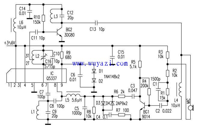
The microphone has a high speech intelligibility, and several measures are taken mainly: the signal output from the MIC is first sent to the BG1 tube for amplification, wherein R1 and C1 are additional high-pitched pre-emphasis circuits. C2 and C3 are the input and output coupling capacitors of the BG1 tube. Their values ​​are used to attenuate the bass and boost the mid-high. The circuit of the diodes D3, D4 and C4, R7 of the BG1 tube output terminal in reverse parallel connection is to limit the strong signal by the characteristic that the internal resistance becomes small when the diode is forward-conducting, and the signal of normal intensity is not affected, and at the same time It also has a good inhibitory effect on the howling caused by the positive feedback between the microphone and the speaker. After the microphone signal is amplified by BG1, it is applied to the varactor inside the IC through L5, and the high-frequency signal is modulated by FM to obtain a large frequency offset.
Breaker Rcbo,Rcbo Protection,Leakage Protection Rcbo,Leakage Protection Switch
ZHEJIANG QIANNA ELECTRIC CO.,LTD , https://www.traner-elec.com