1 Introduction
With the rapid development and maturity of video and broadband access technologies, it has become a reality to watch various live and on-demand programs through IP broadband networks. The time-shifted TV service combines the technical features of live video, video on demand and video recording, so that users can pause, skip back and watch the time, and switch back to live broadcast status from time-lapse viewing while watching TV live broadcast. Look back at the TV shows that have been broadcast. Time-shifted TV has completely liberated users from the traditional passive TV viewing mode of "You broadcast me", and has been listed as one of the basic services by the CCSA IPTV standard. At present, there are two main ideas for implementing time-shifted TV services on broadband networks, namely, IPTV construction scheme based on C/S mode and P2P overlay network scheme based on P2P technology.
In IPTV, time-shifted TV is realized through a combination of live broadcast and on-demand, and its difficulty is similar to video on demand. In the traditional video on demand mode. A connection needs to be established between each user and the video server, so even a limited number of users will quickly exhaust the server's resources. In this way, how to reduce the pressure on the server becomes the key to system design. Many flow scheduling algorithms have been proposed in the industry, such as pyramid algorithm (Pyramid) [1, 2], Skyscraper algorithm [3], Batching technology [4], patching technology [5] ~7] and HierarchICal multicast stream merging (HMSM) [8] technology, etc., the basic starting point of most of the proposed algorithms is to use multicast mode to combine multiple on-demand broadcasts of the same file into one multicast. Channel service. However, these strategies are difficult to be practically used in actual commercial operations. The reason is that the entire network does not support IP-over-network over the entire network, and this resource-saving strategy is based on delaying user response at commercial operation. It’s not worth the candle. Reference [3] proposes a P2P method to implement time-shifted TV transmission strategy, but it is also based on the premise that live broadcast streams use IP multicast transmission, and requires the client to receive both multicast and patch streams. This transmission strategy can be applied to small LAN systems, but not to existing wide area networks. The reason is that the existing wide area network does not support full network IP multicast, and the bandwidth of the most widely used ADSL line is not enough to support the simultaneous transmission of two streams.
On the other hand, in the P2P video system, the video live broadcast service is widely used, such as Cool Streaming, PPlive, etc., while the P2P video on demand system of the scale application is rare, and the P2P system with the time shift TV function is basically not seen. To. However, from the user's point of view, it is the game programs that really attract users to use the P2P video system, such as sports games, super girls games, etc., and users have a strong demand for time shifting of such programs. For example, there is something suddenly happening during the viewing, you need to pause, I hope to continue watching after coming back, or a wonderful shot is not seen clearly, I hope to jump back to watch, or because I have missed the broadcasted program, I hope to be able to watch again, etc. If you can add the time shift function to the existing P2P live broadcast, it will be greatly welcomed by users.
In the past, IPTV and P2P were basically developed independently of each other, and research literature on the combination of IPTV and P2P was rare. Recently, some research literatures on the combination of IPTV and P2P have appeared [8-11], emphasizing the complementary advantages of the two, and discussing how to integrate at the technical level.
This paper will propose a time-shifted TV system using P2P technology. This system not only uses P2P technology to distribute and store live programs, but also does not need to rely on IP multicast technology for live broadcast, so it can solve the time-shift TV service in IPTV system. The problem of high construction cost and poor expansion. In addition, each client only needs to record and store part of the program segment while playing the program, and can provide other clients with the video service being played and the stored program service, so the system proposed in this paper not only reduces each The overhead of the client, and the more participants, the more resources available, the better the quality of service.
2, system solution
2.1 System Architecture
1 is a P2P-based time shift television system architecture. As can be seen from FIG. 1, the system includes a slice processor, a media locator, and a plurality of peer nodes (Peers). The fragmentation processor performs block and segmentation processing on the input live stream to form media partitions and segments. A media segment includes a fixed number of sequentially numbered media segments, the start and end of which are identified by the flag bits in the block header. Media segmentation is the basic unit of system positioning and storage media. Media segmentation is the basic unit of system transmission media. The peer node can obtain block data from multiple other nodes for decoding and playback. For convenience of description, a number of media segments that are continuously scrolling near the play point are defined as a logical special segment - a live segment.
This article refers to the address: http://
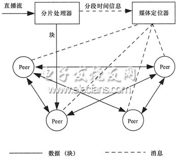
Figure 1 P2P-based time-shifted TV system architecture
The media locator manages the distribution of media segments (including live segments) in the peer nodes and determines whether they are in a serviceable state, and provides the media nodes with location services for the media segments. In addition, the media locator also receives start and end time information for each segment from the slice processor for translation services from time information to segmentation information. For example, a node needs to watch a program at a certain moment of a certain channel, and the node requests a source node from the media locator, and the media locator can obtain a corresponding segment number from the segmentation time information, and returns the service with the segmentation. The source node of the capability.
After receiving the media data, the peer node can be cached in memory and disk. The node reports the uplink and downlink events, the cache segmentation data increase and decrease event, and the node external service capability hopping event to the media locator through the message, whereby the media locator can accurately maintain each media segment on each node. service status. Data transfer takes place directly between peer nodes.
2.2 Data Encapsulation
The media partitioning and segmentation format processed by the fragmentation processor is shown in FIG. 2. The block is composed of a block header and a payload area. The load area stores audio and video frames arranged in chronological order. In addition to describing the frames, the block header includes a channel number, a segment number, a block number, and a segment flag. The segment flag is used to identify the position of the segment in the segment. It can take three values: the beginning of the segment, the middle of the segment, and the end of the segment. With this flag, the peer node can conveniently perform segment delimitation from the segmented stream.
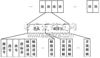
Figure 2 Media segmentation and block encapsulation format
After fragmentation processing, the peer node can obtain different partitions from multiple nodes in the network, splicing and recovering the media stream. Therefore, the node can adopt a flexible and robust multi-source transmission strategy for live broadcast and time-shift service transmission.
2.3 Data Distribution Strategy
The centralized storage server is not used in the system, and all media segmentation data is distributed and stored in each peer node. The peer node does not need to completely record the program during the playback process, but only needs to randomly cache the obtained media segment data in the third-level buffer of the node with a certain probability.
The storage model of the peer node is shown in Figure 3 (where the shaded part indicates that the block already contains data, and the blank block indicates that the block has no data yet), which is divided into a play buffer, a memory buffer, and a disk buffer. The size of the 3 buffers is fixed. The data in the play buffer is constantly scrolling, while being continuously fetched from other nodes, while playing and aging. When the playback buffer has obtained a complete segment, it is written to the memory buffer with a certain probability. When the memory buffer is full, the earliest segment is selected from the stored content, and is overwritten, and the covered segment is placed into the disk buffer with a certain probability. Similarly, if the disk buffer is full, the oldest segment is selected for overwriting.
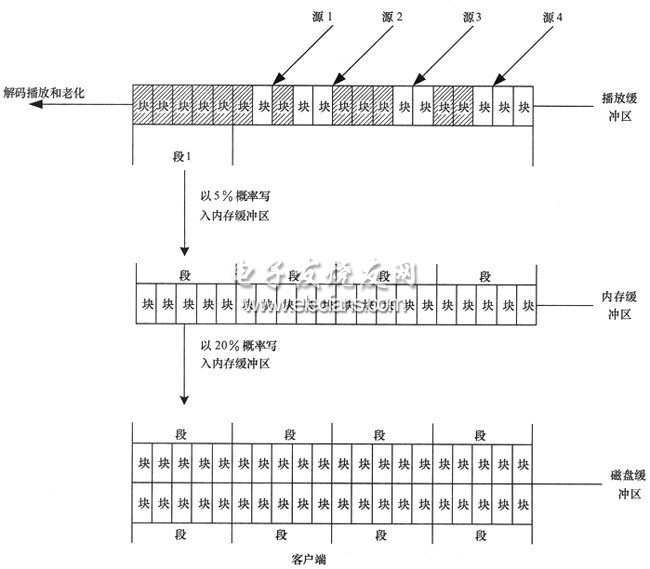
Figure 3 node three-level cache mechanism
Through the above mechanism, the current live segment can be cached in the play buffer, and the copy density in the whole network is the largest; the most recently segmented cache is already in the memory buffer, and the whole network density is second; the older score is Segments are cached on disk, which has a large number of segments but the lowest density. The above processing method can be consistent with the general business viewing habits of the user, that is, most users watch the live broadcast, a small number of users will perform instant time shift, and only a small number of users will watch the broadcasted television programs. In addition, this distribution mechanism has the following effects:
â— There are many people watching a segment, and the probability of being cached in each node of the network is large, and the number of copies of the segment is also large, so that the service capability provided by the segment is larger, so that the segment has a good Scalability
â— A single node only needs to record and store a small number of program segments, so that enough copies of the complete program can be co-stored in the whole network. The larger the number of users, the smaller the recording and storage overhead shared by each user, so it can be effective. Reduce the recording and storage burden of nodes.
3, the process
A brief description of the business process flow of the four major user usage scenarios for time-shifted televisions is given below.

Figure 4 Business process
(1) Live broadcast process
As shown in FIG. 4(a), node A first queries the media locator for the source of the channel P live segment, the locator returns nodes B, C, and D, and node A establishes a connection with B, C, and D to transmit data and decode. Play.
(2) Live time shift
As shown in Figure 4(b), node A is playing channel P. Now the user requests to jump back to time T to play. The process of live broadcast time shift is as follows:
Node A requests the locator for the media segment source node of channel P time T, and the locator returns nodes C and D;
â— Node A stops the transmission of the live segment data, and then establishes a connection with C and D and requests data, and plays from time T;
â— After a segment playback ends, the next segment is played, and the source node of the next segment needs to be re-queried to the locator.
(3) Time shift to live broadcast
Node A is playing time-shifting. The user requests to switch back to the live broadcast. It also needs to query the locator for the source where the live segment is located, then cut off the time-shift segmentation transmission and start live segmentation data transmission.
(4) TV look back
The user directly selects a program for playing the played channel P time T through the web menu, and the principle is similar to the time shift playback in (2).
4. Experimental results
In order to verify the feasibility of the scheme, a system with 20 nodes is built in the LAN. The system parameters are as follows:
â— Code stream: 800 kbit/s, MPEG4, 25 Mbyte/segment, 64 Kbyte/block, 1 channel;
â— Node: 30 Mbyte play buffer, 100 Mbyte memory buffer, 1000 Mbyte disk buffer, the probability of dumping from the play buffer to the memory cache is 10%, and the probability of dumping from the memory cache to disk is 20%. .
The above system was tested and the experimental results are as follows:
â— 20 users live at the same time, can play normally, and the picture is smooth;
â— The time shift to live broadcast switching delay is 0.5 s, and the time delay of live broadcast switching to time shift is 0.5 s;
â— The live broadcast start delay is 0.5 s;
â— Instant time shift can support 0.5 h, and it can achieve smooth switching when 20 users move at the same time;
â— After 20 users are running online for 1 hour at the same time, each user can view the broadcasted TV in the menu mode.
5, the conclusion
This paper proposes a time-shifted TV solution based on P2P technology, which makes full use of the client resources, so the time-shifted TV service can be realized without a dedicated video server, thus solving the high construction cost in the IPTV time-shift TV system. Poor scalability. Experimental verification shows that the proposed scheme has superior user experience quality and good scale scalability.
Lithium Battery Charger,Forklift Battery Charger,Charger For Lithium Ion Battery,Lifepo4 Battery Charger
HuiZhou Superpower Technology Co.,Ltd. , https://www.spchargers.com