With the continuous development of computer technology and measurement and control technology, in the data acquisition system with single chip as the core, it is necessary to realize the data exchange between the single chip computer and the computer, and to take advantage of the advantages of the single chip computer and the computer to improve the performance of the whole system. Price ratio. In computer networks and industrial control systems, serial communication is often required for remote data transmission. Currently, there are a variety of interface standards available for serial communications, including RS232, RS422, RS485, and others. RS232 is the earliest serial interface standard and has been widely used in short-range, low-baud serial communications. However, RS232 communication has the disadvantages of slow transmission speed, short transmission distance, and easy signal interference, and its application limitations have become increasingly prominent. RS485 communication uses differential method to eliminate noise, that is, the signal is decomposed into positive and negative lines before transmission. When the receiver arrives at the receiving end, the signals are subtracted, so that the noise cancels each other and restores the original signal. The mode interference suppression capability is strong and has been widely used in industrial control and other fields.
To realize RS485 communication between the MCU and the computer, generally two methods can be used: one method is to use RS232 and RS485 level conversion devices on both ends of the MCU and the computer respectively; the other method is to use RS485 communication card, and It is plugged into the computer motherboard. The advantage of using the former method is that the hardware device is easy to install and the software programming is relatively simple; the disadvantage is that the communication rate is limited to 20 kb/s. The advantage of the second method is that the communication distance is relatively long and the rate is high, up to 10 Mb/s; the disadvantage is that the communication card and driver need to be installed and necessary settings are made. This article uses the second method.
Circuit design
The UART serial bus is used for communication, because UART is a serial transmission interface widely used in long-distance, low-rate, low-cost communication. Due to its low data line, it has been widely used in digital system design. The basic UART communication only needs two data lines (RXD, TXD) to complete the data communication, and the receiving and transmitting are all full-duplex, in which RXD is the receiving end and TXD is the transmitting end.
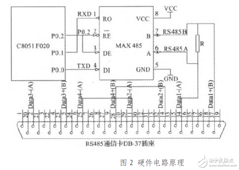
The C8051F020 microcontroller has two UARTs (UART0 and UART1). Take UART0 as an example. Its TxD and RXD are multiplexed with the digital I/0 pins PO.O and PO.1, respectively, and selected by the crossbar configuration register. Since the MAX485 operates in a half-duplex state, it is relatively simple to connect to a microcontroller. It is only necessary to use one of the microcontroller pins (such as PO.2) to control the two pins RE and DE. The PCL-846B communication card has 4 channels, select channel 1 to communicate with the MCU, and connect channel 2 and channel 4 to realize the self-test of the communication card in a self-sending manner. The connection relationship between the microcontroller and the external circuit is shown in Figure 2.
When communicating with an RS485 communication card, when the signal is transmitted to both ends of the communication line, if the impedance does not match, a signal reflection problem may occur. Signal reflections can cause distortion and distortion of the signal, resulting in communication errors. The solution is to connect a terminal matching resistor at each end of the communication line to ensure impedance matching. When the communication distance is short, generally less than 300 m, the terminating resistor may not be used. When the communication distance is greater than 300 m, the terminating resistor should be used, and its resistance must be the same as the linear impedance of the communication line. The resistance value is generally selected to be about 120 Ω. When the communication distance is long, 300 Ω can be selected.
Solid State Relay(SSR )
YANGZHOU POSITIONING TECH CO., LTD. , https://www.cnfudatech.com