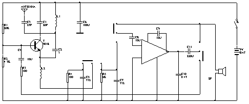
The FM intercom circuit introduced here has an intercom distance of more than 100m in an open area , and can be used with a FM radio in conjunction with a wireless microphone.
The circuit is shown in the figure. Transistor V and inductance coil L1 , capacitors C1 , C2, etc. form a capacitive three-point oscillation circuit that generates a carrier frequency signal with a frequency of approximately 100MHz . The circuit LM386 and capacitors C8 , C9 , C10 , Cll, etc. form a low-frequency amplifier circuit. The speaker BL doubles as a microphone. When the circuit is working in the receiving state, the receiving / transmitting switch is placed in the "receiving" position. The signal received from the antenna ANT passes through the transistor V , the inductor L1 , the capacitors C1 , C2, and the high-frequency choke L2 . The regenerative detection circuit detects. The detected audio signal is coupled to the input terminal of the low-frequency amplifier through the capacitor C8 , and after being amplified, the capacitor C11 is coupled to drive the speaker BL to sound.
When the circuit works in the signal sending state, S2 is placed in the "signaling" position, and the speaker turns the voice into an electrical signal. After the IC is amplified at a low frequency, the output coupling capacitors Cll , S2 , R3 , C4, etc. add the signal to the oscillator The base of V makes the bc junction capacitance of the tube change with the change of the voice signal, and the bc junction capacitance of the tube is connected in parallel at both ends of L1 , so the frequency of the oscillation circuit also changes accordingly, realizing the function of frequency modulation And transmit the modulated wave from the antenna through the capacitor C3 .

V selects silicon high-frequency small power tubes with fT> = 600MHz and B> = 60 , such as 3DG80 and 3DG56 . L1 is wound with 0.8mm enameled wire in 6 turns, with an inner diameter of 6mm , and then elongated into a hollow coil with a pitch of 1mm . L2 is made of 0.lmm enameled wire wound around l00 circle on 1 / 8W , 100K resistance . C1 , C2 , C3 use mica or high frequency ceramic dielectric capacitor. S2 uses four-pole two-position toggle switch. BL selects electric horn with a diameter of 5cm . The antenna uses a 0.8- meter whip antenna (when used as a wireless microphone, multiple flexible cords of the same length can be used instead). The power supply uses 9V laminated battery. The parameters of the two radios should be as consistent as possible.
When debugging, first put S2 in the "receive" position, then the speaker should have a large noise. Touching the noise of the triode casing with your hand indicates that the receiving circuit is working normally. Then put S2 in the "signaling" position, take a FM radio nearby, and adjust the receiving frequency to about 100MHz . At this time, there should be a loud howling in the radio, and the howling disappears when it is about 10 meters away , Talk to the microphone, you should be able to hear a clear, loud sound on the radio. If there is no sound or the sound is low, you can adjust the radio frequency. After the two interphones have completed the above-mentioned debugging, conduct an intercommunicability test, and adjust the spacing of L1 appropriately so that the receiving and sending can be unified to the same frequency. When the frequency of the local radio station overlaps, the resonance capacitor C1 needs to be replaced to prevent mutual interference and affect normal use.

Follow WeChat

Download Audiophile APP

Follow the audiophile class
related suggestion
![[Photo] Analysis of FM transmitter module C2](http://i.bosscdn.com/blog/20/06/41/521048165.jpg)
![[Photo] A walkie talkie circuit](http://i.bosscdn.com/blog/20/06/41/5205822650.gif)
The circuit is shown in the figure. This circuit uses Japanese NE ...
![[Photo] FM wireless microphone](http://i.bosscdn.com/blog/20/06/41/5204453888.gif)
![[Photo] FM wireless microphone (upc1651)](http://i.bosscdn.com/blog/20/06/41/5203934420.gif)