Low frequency power amplifier |
| Power amplification is an energy conversion circuit. Under the effect of the input signal, the transistor converts the energy of the DC power supply into output power that varies with the input signal to the load. The requirements for power amplification are as follows: (1) The output power should be large: To increase the output power of the amplifier, the transistor must be operated near the limit working area, which is determined by ICM, UCM and PCM. See Figure 1. |
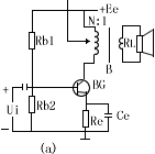 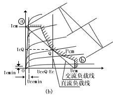 Figure 1 |
| (2) The efficiency η is higher: the efficiency η of the amplifier is defined as: η = AC output power / DC input power (3) The nonlinear distortion is within the allowable range: Because the power amplifier works under a large signal, nonlinear distortion is inevitable The problem is to control the distortion within the allowable range, The power amplifier can be divided into the following types according to the working state and circuit form: (1) Class A power amplifier: During the entire signal period, there is collector current; (2) Class B power amplifier: within half a signal period, there is a collector current, which can be divided into: 1) Double-ended push-pull circuit (DEPP) 2) Single-ended push-pull circuit (SEPP) 3) Balanced transformerless circuit (BTL) In practice, in order to overcome the crossover distortion, the push-pull Chang body tube circuit is working in Class A and B states. |
| 1. Class A power amplifier |
Figure 1 is a class A power amplifier, the load RL becomes the collector load RL = n through the impedance converter B |
| It can be seen that: (1) The maximum collector voltage of the transistor is twice the power supply voltage EC. (2) The static power consumption of the transistor is twice the output power. (3) The maximum efficiency of Class A amplifier is only 50%. |
| 2. Class B push-pull circuit |
| Figure 2 (a) is a class B push-pull circuit. Because the output uses a transformer, the transistor has two output terminals to ground. The circuit is completely symmetrical. When the input signal Us is a positive half wave, BG1 is turned off and BG2 is turned on. The voltage UL is a negative half-wave. Therefore, the two tubes are turned on in turn and work with one push and one pull, so it is called a push-pull circuit. Since the two tubes work alternately, the output characteristics of the two tubes are stacked together in opposite directions. The AC load lines of the two tubes are connected in a straight line ab, and the operating point Q is at the midpoint of the straight line ab, as shown in Figure 2 (b). It can be seen from the figure that the relationship between the amounts of electricity: (1) If the turns ratio of the primary and secondary windings of the output transformer is n, then the load resistance RL of each transistor is: RL = (n / 2) The resistance RCC between the collector and the collector is Rcc = n (2) The voltage amplitude of the primary winding end of transformer B2 is: Ucem = UceQ≈Ec --------------------------------------------- ------- Form 8 The primary winding current amplitude is: Icm = IcM ----------------------------------------------- ----------- Form 9 So the power delivered to the primary winding is: Ps = (Ucem / (3) The average value of the current through each transistor is: Ico = IcM / π --------------------------------------------- ---------- Form 11 The power supplied by the DC power supply is PD = (2Ico) Ec = 2 × (Icm / π) × Ec ---------------------------------- ---- Form 12 (4) The efficiency of the push-pull circuit is: η = (Ps / PD) 100% = {(1/2 × Ec × Icm) / [2 × (Icm / π) × Ec]} 100% ≈78.5% ----- Equation 13 Pay attention to when designing the push-pull circuit: (1) To avoid crossover distortion, the transistor should have a certain bias current, but not too large, otherwise the circuit efficiency will be reduced. (2) The maximum collector voltage of the transistor Ucm> 2Ec. (3) The dissipated power of the transistor Pcm≥1.2Pc1, where Pc1 is the power that each transistor sends to the transformer B2 primary, that is, Pc1 = [(1/2) Pso]. (4) According to the requirements of Pc1 and Ec1, calculate the transistor load resistance PL and the turns ratio n of the output transformer. |
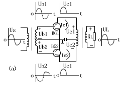 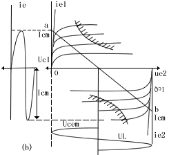 figure 2 |

Follow WeChat

Download Audiophile APP

Follow the audiophile class
related suggestion
Avago Introduces New High Linear Power Amplifier Module Product Avago Technologies ...
The circuit is shown in Figure 1. The chip IC uses the LM1875 of the American NS company, which has a soft tone and low distortion (0.015% ...
The word "Monster" has both positive meaning and ...
When the output power of the digital power amplifier is greater than 50W, it is impossible to use only ...
If an "audiophile" is a group of people who are never satisfied with the sound and "loved the new and the old" with the audio equipment. Then just rely on these so-called "fever spirits" ...
First, the circuit principle and characteristics 1. Power amplifier part (see Figure 1)
There is a well-known saying in the Hi-Fi world that is "briefness first." This means that if ...
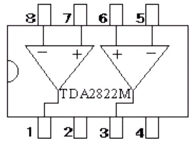
Simple and practical TDA2822M integrated power
TDA2030 is ...

STK465 thick film ...

This RF power amplifier can output 2-3 channel signals, covering an area of ​​about one square kilometer, is ...
![[Photo] 15w RF power amplifier](http://i.bosscdn.com/blog/20/06/41/521040781.gif)
![[Photo] Broadband high frequency power amplifier](http://i.bosscdn.com/blog/20/06/41/520536801.jpg)
![[Photo] TDA2030 audio power amplifier](http://i.bosscdn.com/blog/20/06/41/5131012891.gif)
Looking at the Hi-Fi amplifiers currently on the market, the output power is 100W ...
![[Photo] Transistor 15W Class A Power Amplifier](http://i.bosscdn.com/blog/20/06/41/513102891.gif)
With the newly launched LM4651 and LM465 from National Semiconductor ...
![[Photo] 125W Class D Subwoofer Power Amplifier](http://i.bosscdn.com/blog/20/06/41/513100868.jpg)
![[Photo] Mark Levinson No. 30 ...](http://i.bosscdn.com/blog/20/06/41/513544752.jpg)
EL34 (6CA7) was first launched by Philips in 1956 ...
![[Photo] 45W transistor tube hybrid power amplifier](http://i.bosscdn.com/blog/20/06/41/513531952.jpg)
This article cleverly combines the electronic tube EL34 and the transistor (op amp), ...
![[Photo] 32W hybrid audio power amplifier](http://i.bosscdn.com/blog/20/06/41/513526493.jpg)
The pre-amplifier adopts a European-made TESLA brand low noise high cheek double transistor ...
![[Photo] Gallstone hybrid power amplifier using switching power supply](http://i.bosscdn.com/blog/20/06/41/513524776.gif)
"Simple" means the circuit of the amplifier is simple, making it easier, as long as the picture ...
![[Photo] Simple fool power amplifier](http://i.bosscdn.com/blog/20/06/41/513432946.jpg)
1. Description: & nb ...
![[Photo] LM386 low voltage audio power amplifier ...](http://i.bosscdn.com/blog/20/06/41/513417261.gif)
The Class A transistor power amplifier has a warm and sweet tone, which makes people tempted. But the temperature rise of Class A amplifier ...
![[Photo] Class A power amplifier using SAP15N / P audio pair tube ...](http://i.bosscdn.com/blog/20/06/41/513346769.gif)
The circuit is shown in Figure 5, ...
![[Photo] Using TDA7294 and 2SA1216 / 2S ...](http://i.bosscdn.com/blog/20/06/41/4233420295.gif)
'+ data.data.username +' '; dom + ='
Portable charger which is also named Power Bank or portable phone charger is popular for charging smart phones and mobile tablet devices. Our portable phone battery charger is compatible with most of the mobile phones in the market . there is no need to worry compatibility if you want to use by yourself or send as a gift .
Provide best power bank.
Perfect compatibility
Our power bank is compatible with most of the mobile phones in the market .
There is no need to worry compatibility if you want to use by yourself or send the Powerbank Phone Charger as a gift.
Share together , more friend ship
Ultra slim and easy to carry
Genuine Portable Battery Mobile Power Bank Charger
Li-Polymer with LED Indicator
Li-polymer battery
Customized the shape
Ultra thin power bank adopts Li-polymer cell inside
High safety performance
Li-polymer cell will not explode
The portable battery charger is designed more friendship , and is Built-in intelligent protect chip to prevent overcharge . we aim to provide the best portable charger for customers .
The advantages of this produce as following :
Ultra thin and easy to carry
High capacity
Dual input & dual output
Dual output more convenient
Both apple and android user can charge and recharge with either micro cable or Lightning Cable .
Power Bank
Power Bank, Power Bank Charger, Powerbank Phone Charger, Power Bank Battery, Portable Battery, Phone External Battery
Hebei Baisiwei Import&Export Trade Co., LTD. , https://www.baisiweicable.com