Analyzed the terminal voltage waveforms of the upper bridge arm PWM modulation and the lower bridge arm constant-pass modulation mode, and discussed the corresponding back-EMF zero-crossing detection method. At the end of the PWM modulation signal on state, the terminal voltage is sampled, and the back-EMF is determined by the software algorithm Zero-crossing point. In view of the situation of leading or lagging commutation when the motor is running, the optimal commutation can be achieved by setting a reasonable delay time. In view of the uneven distribution of back-EMF zero-crossing points in the actual motor, according to the zero-crossing interval time There is a periodic law, a new delay time setting method is proposed, so that the commutation point is located in the middle of the adjacent zero-crossing points, which realizes the accurate commutation of the motor. The experiment verifies the feasibility and effectiveness of the proposed method.
Brushless DC motors (BLDCM) have the advantages of simple structure, high operating efficiency and good speed regulation performance, and are widely used in industrial and commercial fields. In recent years, the position sensorless control of brushless DC motors has been a research hotspot at home and abroad. , The more common rotor position signal detection methods include back electromotive force method, stator inductance method, freewheeling diode method, flux estimation method and state observer method, among which back electromotive force method is the most effective and practical.
When the speed is fast, the back EMF is detected during the PWM off and on phases, and two different reference voltages are used to obtain the zero-crossing point of the back EMF, without the need for a position sensor and a current sensor, but it increases the complexity of the hardware circuit. The literature compares the suspension The relationship between the phase winding terminal voltage and the midpoint voltage of the inverter DC loop to obtain the zero-crossing point of the back electromotive force. This method does not need to reconstruct the neutral point of the motor, and does not use a filter circuit, but a hardware circuit is required to compare the zero-crossing point.
A method for detecting the zero-crossing point of back-EMF in the on _pwm modulation mode is proposed. A microcontroller with built-in AD is used to detect the floating phase terminal voltage when the PWM is turned on. The software algorithm uses simple algebraic operations to obtain an accurate zero-crossing signal. At present , The research on the back-EMF method mostly focuses on the detection circuit method of the back-EMF zero-crossing point and the elimination or compensation method of the phase error caused by the filtrate circuit, but the research on accurate commutation is not deep enough.
1 Principle of Direct Back-EMF
Brushless DC motors generally adopt the "two-phase conduction, three-phase six-state" operation mode, each working state only two-phase windings are turned on, and the third-phase winding is in the floating state, which is used to detect the zero-crossing point of the back EMF. After the back-EMF zero-crossing point, the corresponding delay time is set according to the commutation point lagging the zero-crossing point by 30° electrical angle. When the delay time is reached, the motor commutates into the next working state.
In this paper, a direct back-EMF detection circuit based on terminal voltage is used to obtain the zero-crossing point of back-EMF by detecting the terminal voltage signal of the dangling phase winding. The voltage divider resistor is used to divide the terminal voltage and the DC side voltage in the same proportion, so that the divided voltage The measured signal falls within the allowable input range of the sampling unit. Figure 1 (a) Main circuit and direct back-EMF voltage divider circuit, the terminal voltages UA, UB, UC and UDC are divided into Ua, Ub, Uc, respectively And Udc.
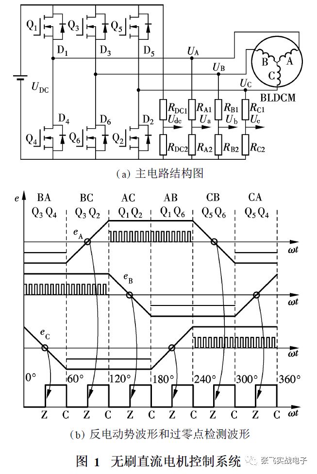
The ideal back-EMF waveform is a positive and negative alternating trapezoidal wave, and the center point of the motor is used as the reference point. In Figure 1 (b), eA, eB, and eC represent the three opposite electromotive forces. The motor has a total of 6 operations in one cycle State, the working state changes once every 60° electrical angle, and each power switch is turned on by 120° electrical angle. The working state can be represented by the two-phase windings and 2 power switches that are turned on, as shown in Figure 1 (b), BA indicates that the current flows in from the B-phase winding and flows out from the A-phase winding; Q3Q4 indicates that the two power switches of the B-phase upper arm and the A-phase lower arm are turned on. The zero-crossing detection waveform indicates the back-EMF zero-crossing and commutation points, Among them, Z is the back-EMF zero-crossing point, and C is the commutation point. The back-EMF zero-crossing points and the commutation points are evenly distributed, and are separated by an electrical angle of 30°.
2 Back-EMF zero-crossing detection method
Brushless DC motor control can use a variety of PWM modulation methods. The modulation methods used are different, and the terminal voltage waveforms presented are also different. This article uses the upper-side arm PWM modulation and the lower-side arm constant-on (H _pwm 2L _on) modulation method. Take phase A as an example, assuming that the PWM duty cycle is 50%, ignoring high-frequency switching noise and pulse glitches generated by commutation freewheeling, the ideal terminal voltage waveform is shown in Figure 2 (a). Within a period, the The voltage waveform at the A phase terminal is divided into six areas BA, BC, AC, AB, CB and CA, and each area corresponds to a working state. The rising and falling parts of the terminal voltage waveform are the BC area and the CB area. In a suspended state.
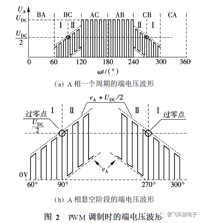
The BA and CA areas are the conduction phase of the lower bridge arm switch of phase A. Q4 is in a constant on state. The phase A winding is connected to the negative pole of the DC side voltage, and the terminal voltage is clamped to the negative potential of the DC side voltage. Because the negative pole of the DC side voltage is The reference point of the terminal voltage, when the terminal voltage is zero.
The AC and AB areas are the PWM modulation phases of the A-phase upper arm switch. Take the AC area as an example, during the PWM on period, Q1 and Q2 are turned on, and the A-phase winding is connected to the positive pole of the DC side voltage, and the terminal voltage is UDC; in the PWM During the shutdown period, Q1 is closed and Q2 is turned on. Because the winding impedance is inductive, the anti-parallel diode D4 of the lower arm of the A phase is conducting freewheeling. At this time, the phase A winding is connected to the negative pole of the DC side voltage, and the terminal voltage is zero.
Zones BC and CB are the phases of phase A floating, and the two zones are divided into two periods I and II respectively, as shown in Figure 2 (b). Take the BC zone as an example, at this time, the current flows in from the phase B winding, and C The phase winding flows out, as shown in Figure 3. In the figure, RS and LS represent the equivalent resistance and inductance of the stator winding respectively, UN is the voltage at the center point of the motor, and i is the phase current. Ignore the forward voltage drop of the power switch and the diode , According to Kirchhoff's voltage law
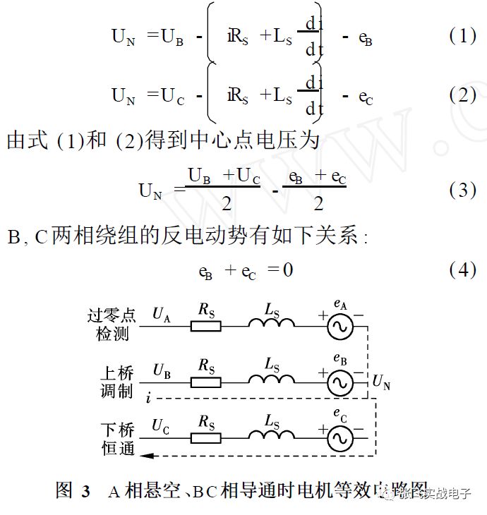
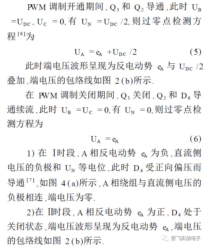
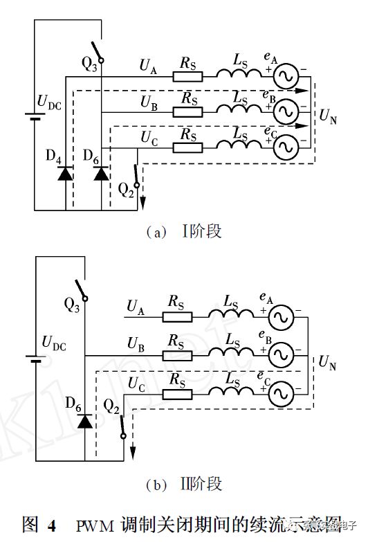
In this paper, the terminal voltage of the floating phase is sampled at the end of the PWM modulation on state. Due to the delay effect of the hardware circuit, the power switch has not been turned off during sampling, which is equivalent to sampling during the PWM modulation on period. At this time, the sampled voltage signal is affected by The influence of switching noise is small. According to formula (5), when the voltage value of the phase A terminal is detected to be half of the DC voltage value, the opposite electromotive force of A crosses zero, and the comparison of UA and UDC /2 is equivalent to the comparison of eA and 0.
The back-EMF zero-crossing detection method is simple and accurate, and the software algorithm is used to determine the back-EMF zero-crossing point. As long as the hardware circuit selects a resistor with appropriate resistance and power for voltage division, there is no need to reconstruct the center point of the motor, and no low-pass filter is required. , The signal has no phase delay, and no comparator is used to detect the zero-crossing point. The hardware circuit has a simple structure and is suitable for low-cost applications.
3 Delay time setting method
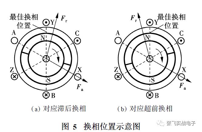
The optimal commutation logic means that the winding is turned on at the flat top part of the trapezoidal wave back EMF, and the corresponding optimal commutation position means that after the commutation is completed, the stator magnetic potential leads the rotor magnetic potential by 120° electrical angle, such as As shown in Figure 5. Among them, Fa and Fr represent the stator magnetic potential and the rotor magnetic potential, respectively. In a working state, the stator magnetic potential leads the rotor magnetic potential by an average of 90° electrical angle, and the average electromagnetic torque is the largest.
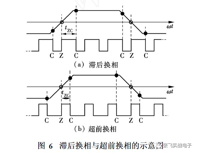
If the rotor has turned to the optimal commutation position at the time of commutation, it will behave as lagging commutation. Annihilation, the delay time tZC from the zero crossing point to the commutation point is too large, as shown in Figure 6. When lagging commutation, the angle of the rotor exceeding the optimal commutation position should be less than 30° electrical angle. If the commutation is seriously lagging, the next time The zero-crossing point will be annihilated and cannot be detected, causing the motor to lose step. On the contrary, if the rotor does not reach the optimal commutation position, it is commutation, it is advanced commutation, and the commutation point is relative to the optimal commutation position on the time axis. Shifting to the left, the part of the left side waveform of the terminal voltage is annihilated, and the delay time tZC from the zero crossing point to the commutation point is too small. Both the lag commutation and the lead commutation will cause the electromagnetic torque of the motor to fluctuate, and the rotor will not run smoothly. The measured terminal voltage The waveform (channel 1) is shown in Figure 7.Channel 2 is the zero-crossing point detection waveform, and the rising edge and the falling edge correspond to the zero-crossing point and the commutation point, respectively.
According to the principle that the zero-crossing point leads the commutation point by 30° electrical angle, after the zero-crossing point is detected, the delay time tZC is set to determine the commutation point. In an ideal operating state, the zero-crossing point and the commutation point are equally spaced, and the difference between each other is 30°. Angle. Therefore, the delay time can be set according to the interval time of the zero crossing. The traditional delay time setting method is to set the delay time to half the time from the last zero crossing to the current zero crossing, as shown in Figure 8. In the figure, Z (k) and C (k) represent the k-th zero-crossing point and the k-th commutation point respectively. When the k-th zero-crossing point is detected, the delay time is set as follows:

In the formula, TZZ (k-1) is the time from the k-1 zero crossing to the k zero crossing; tZC (k) is the delay time from the k zero crossing to the k commutation point.
Load the set delay time into the register, and the counter starts timing. After reaching the preset delay time, the motor commutates into the next working state, and the stator magnetic potential is stepped once. The commutation point is located in the middle of the adjacent zero-crossing points, The motor replaces the phase at the best commutation phase, the average electromagnetic torque is the largest, and the terminal voltage waveform is symmetrical. When the back-EMF zero-crossing points are evenly distributed, the traditional delay time setting method can better realize the positionless brushless DC motor Sensor control.
4 New delay time setting method
The back-EMF method focuses on detecting the two zero-crossing points of the rising and falling parts of the back-EMF waveform. The flat top part of the waveform has little effect on the zero-crossing detection method. Due to the influence of the motor manufacturing process and other aspects, the actual brushless DC motor has three phases The winding is not completely symmetrical, resulting in differences between the three opposite electromotive forces, the interval time between adjacent zero crossings is not completely equal, and the zero crossing distribution is not uniform.
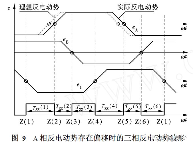
Assuming that there is a phase shift in the reverse electromotive force of A, the zero-crossing points on the rising and falling parts of the waveform appear lagging, causing the zero-crossing points to be unevenly distributed on the time axis. As shown in Figure 9, the dashed line represents the ideal back EMF, and the solid line represents the phase shift The actual back-EMF shifted, the zero-crossing interval time TZZ (1), TZZ (2) and TZZ (3) are not equal. The two zero-crossing points of the rising and falling parts of the opposite electromotive force waveform differ by 180° electrical angle, and the zero-crossing interval Time has periodic laws, such as TZZ (1) = TZZ (4), TZZ (2) = TZZ (5) and TZZ (3) = TZZ (6).
Using the traditional delay time setting method, some commutation points deviate greatly from the ideal commutation point. When a commutation is seriously lagging, the next zero crossing point is easily annihilated, causing the motor to lose step, as shown in Figure 10.
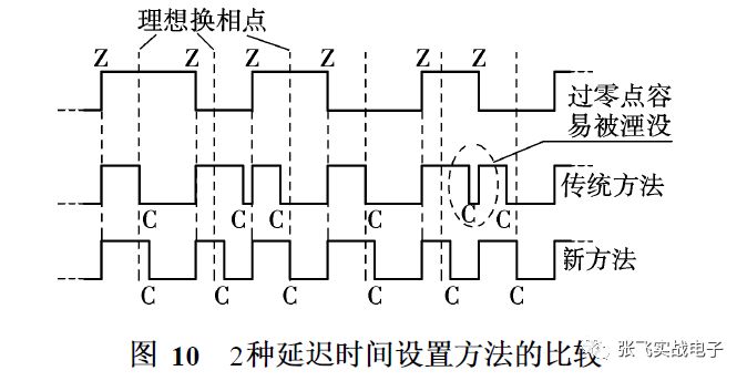
In order to make the commutation point located in the middle of the two adjacent zero-crossing points, this paper proposes a new delay time setting method. As shown in Figure 11, the zero-crossing interval TZZ (k-3) and TZZ (k) are equal , When the k-th zero-crossing point is detected, the delay time tZC (k) from the k-th zero-crossing point to the k-th commutation point is set as follows:

In the formula, TZZ (k-3) is the time from the k-3 zero crossing to the k-2 zero crossing.
When the interval time length of the three opposite electromotive force waveforms is not the 120° electrical angle expected by the new delay time setting method in Fig. 11, and the zero crossing interval time is not equal, the new delay time setting method can make the commutation more accurate. The phase point falls in the middle of the two zero-crossing points before and after. The zero-crossing point is not easy to be annihilated, and the motor is not easy to lose step, as shown in Figure 10. Especially when the motor is running at high speed, the new method improves the reliability of the motor operation. The experiment well verifies the feasibility and effectiveness of the new method.
The measured terminal voltage waveforms (channel 1) corresponding to the two delay time setting methods are shown in Figure 12. Channels 2 and 3 are the zero-crossing detection waveforms. The rising and falling edges of channel 2 correspond to the zero-crossing point, and the channel 3 The rising edge and the falling edge correspond to the zero crossing point and the commutation point respectively.
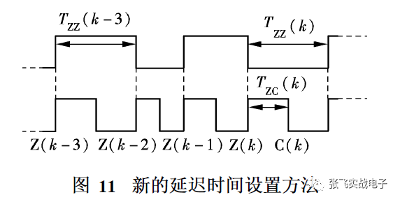
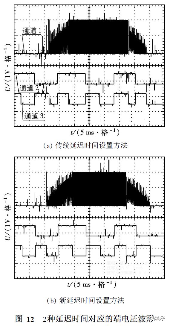
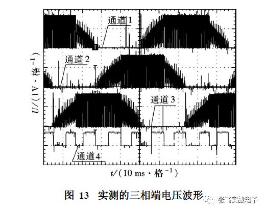
Figure 13 shows the measured three-phase terminal voltage waveforms (channel 1 to channel 3). The rising and falling edges of channel 4 correspond to the zero-crossing point and the commutation point, respectively.
5 Conclusion
1) The back-EMF method obtains the zero-crossing point of the back-EMF by detecting the terminal voltage, and sets the delay time to obtain the commutation point. This paper uses a software algorithm to obtain the zero-crossing and commutation points, which simplifies the hardware circuit and is suitable for low-cost applications.
2) Leading commutation or lagging commutation will cause the motor to run unevenly, and the waveforms on both sides of the terminal voltage are asymmetrical.By setting a reasonable delay time, the motor can be replaced at the best commutation phase.
3) When the back-EMF zero-crossing points are evenly distributed, the traditional delay time setting method can be used, that is, the delay time is set to half of the time from the last zero-crossing point to the current zero-crossing point.
4) When the zero-crossing points of the actual back-EMF of the motor are not uniformly distributed, the delay time from the k-th zero-crossing point to the k-th commutation point can be equal to half of the time from the kth-3rd zero crossing to the k-2nd zero crossing point. This new delay time setting method enables the commutation point to be located in the middle of the two adjacent zero-crossing points, which realizes the accurate commutation of the motor. The experiment has well verified the feasibility and effectiveness of the new method.
Commercial Electric Fan,Small Electric Fan,Standard Electric Fan,Electrical Fan
Foshan Shunde Josintech Electrical Appliance Technology Co.,Ltd , https://www.josintech.com