1. Reasons for positioning interference
When the bus has interference, experienced engineers can quickly locate it, but it is very troublesome for novices. There are many reasons for bus interference, such as coupling into communication cables through electromagnetic radiation, improper grounding of shielding wires, and isolated communication without isolated power supply. From the figure below, we can deduce that the on-site interference does not come in through electromagnetic radiation, and the vehicle’s network has no interference. It can basically be concluded that the interference is that the CAN communication of the motor driver is not well isolated.

Figure 1 Causes of positioning interference
Two, the method to eliminate the delay error
In order to reduce the delay, increase the communication distance and reduce the communication error rate, we can take the following measures:
Design the interface transceiver circuit with the magnetic isolation CTM1051 scheme;
Use thicker wires instead of thin wires, the standard is 1.5 cables (delay 5ns/m);
Use gold-plated or silver-plated cables;
Increase the CANBridge relay device to extend the communication distance;
Using optical fiber transmission, such as the CANHUB-AF1S1 of Zhiyuan Electronics, the same baud rate can extend the communication distance by 1 times.
3. Signal ground (CAN-GND)
1. The concept of signal ground
The signal ground is also called the isolation ground. In order to make the electronic equipment have a unified reference potential when working, avoid the interference of harmful electromagnetic fields, and make the equipment work stably and reliably, the signal circuit in the equipment has a unified reference ground, namely CAN-GND.
2. Signal ground processing
In many practical applications, designers often directly connect the reference ground of each node to the local ground as the return ground of the signal. This seems to be normal and reliable, but there are great hidden dangers!
The correct connection of the signal ground (CAN-GND) is mainly divided into two types:
Single-shielded cable: If the cable is a single-shielded cable, the ideal connection method for signal ground is to use a dedicated signal wire to connect the signal grounds of all nodes to serve as a reference ground. However, if there is a lack of signal ground wire, all node signal grounds can also be connected to the shielding layer, but the shielding effect is not satisfactory.
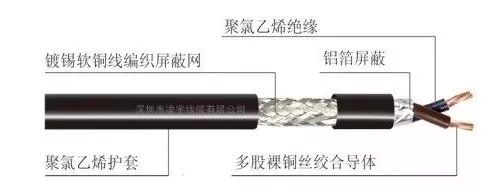
Figure 2 Shielded twisted pair cable
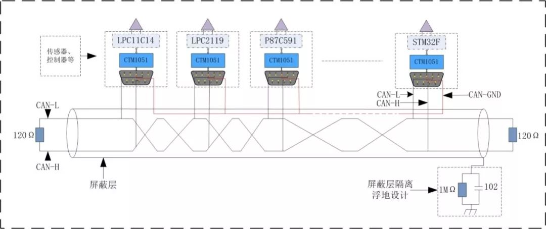
Figure 3 Connection mode of twisted pair with signal ground
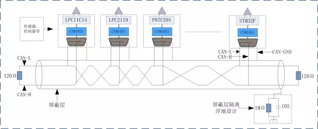
Figure 4 Connection mode of signal ground and shielding layer
Double-shielded cables: When double-shielded cables are used, the signal grounds of all nodes need to be connected to the inner shield. If unshielded cables are used for data transmission, please keep the signal ground pins floating.
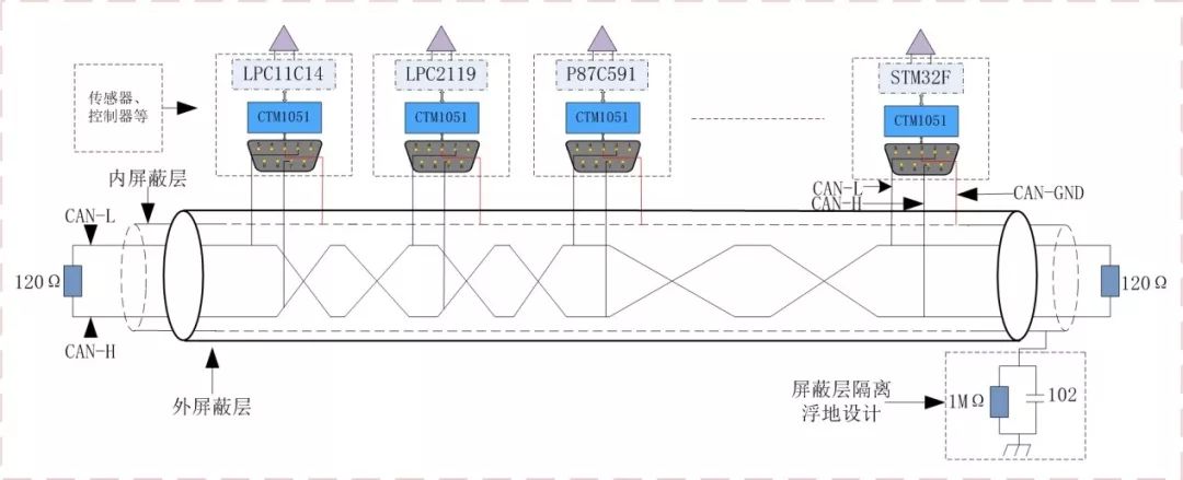
Figure 5 Signal processing method of double shielding layer
After the signal grounds of all nodes are connected to the shielding layer or the inner layer of the double shielding layer, the shielding layer should be treated as a single-point grounding, not multiple grounding points, otherwise a ground circulation will be formed on the signal ground.
In addition, in order to increase the isolation resistance between the power supply ground and the signal ground when single-point grounding, and prevent electromagnetic interference caused by the coupling of the common ground impedance circuit, pay attention to the isolation floating ground design, and the shielding layer and the shell are isolated by the resistance-capacitance method.
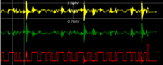
Figure 6 Messages without single-point grounding are subject to electromagnetic interference
Ec Backward Centrifugal Fan,Backward Centrifugal Fan,Backward Curved Centrifugal Fan,Backward Inclined Fan
Hangzhou Jinjiu Electric Appliance Co Ltd. , https://www.jinjiufanmotor.com