The motor is an important executive component of various CNC machine tools. To achieve precise position control of the motor, the position of the rotor must be accurately detected. Photoelectric encoders are the most commonly used detection devices at present. Photoelectric encoders are divided into incremental, absolute and hybrid. Among them, the incremental type has been widely used because of its simple structure, long mechanical life, and easy to achieve high resolution. Incremental photoelectric encoder outputs A, B, Z three-phase signals, in which the phase difference between A and B is 90°, and Z is the "zero position" of the encoder, and only one pulse is output per revolution. In applications, it is often necessary to divide the A-phase and B-phase quadrature pulses according to a certain ratio, that is, the cycle division ratio. The difficulty of frequency division is that no matter whether the set cycle ratio is an integer or a fraction, the A'-phase and B'-phase pulses output after frequency division still have to remain in quadrature or approximately quadrature. To this end, an FPGA-based integer cycle ratio implementation method is proposed. The method has the advantages of simple logic structure, flexible configuration, easy expansion and high practical value.
1 Electronic gear ratio and cycle ratio
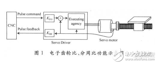
Electronic gear ratio and cycle ratio are a very important concept in CNC machine tools and CNC machining centers. Most of the foreign servo drives have the functions of electronic gear ratio and cycle ratio, among which the electronic gear ratio KEG is the ratio of the pulse amount actually executed by the servo motor to the command pulse amount, and the cycle ratio KDF is the servo drive received from the servo motor shaft. The ratio of the pulse amount of the pulse encoder to the actual pulse amount fed back to the upper servo control system (CNC). With the use of electronic gear ratio and cycle ratio functions, users can easily achieve integer pulse equivalents, so as to avoid quantization errors in intermediate calculations. Machine tools or machining centers with different lead screws.
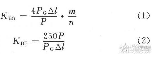
The electronic gear ratio and the dividing ratio can be calculated according to the following formula.

In the formula: PG is the line number of the motor photoelectric encoder, the unit is P/rev (pulse/rev); P is the lead screw pitch, the unit is mm/rev (mm/cycle); â–³l is the pulse equivalent, the unit is mm/ P (mm/pulse); m/n is the reduction ratio.

The electronic gear ratio can be realized by the conversion of the pulse frequency, and for the cycle ratio, since the pulse amount fed back to the CNC by the driver generally adopts an orthogonal pulse sequence, the realization of the cycle ratio is more difficult than the gear ratio. Various foreign drivers generally have the function of dividing the cycle. The use of FPGA to realize the cycle-by-cycle ratio is studied and discussed. The schematic diagram of the electronic gear ratio and the cycle-by-cycle ratio is shown in Figure 1.

Schematic diagram of the 2-cycle ratio
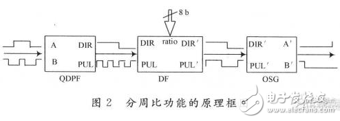
The realization structure of the cycle ratio function is shown in Figure 2.

The realization of the cycle ratio requires three functional modules: the quadruple frequency module QD-PF, the frequency division module DF, and the orthogonal sequence generation module OSG. The input of the QDPF module is the quadrature pulse sequence, and the output is the direction signal and the pulse after the quadruple frequency. The DF module can realize the frequency division of the input pulse by three. Inside DF is an up-down counter, which counts up and down according to the input direction signal, and outputs a pulse and a positive direction signal after the positive count reaches the set positive threshold, and outputs a pulse and a positive direction signal after the negative count reaches the set negative threshold. Negative direction signal. When the count value is between the positive and negative thresholds, even if the motor direction changes or even shakes, the output direction signal remains unchanged.
The OSG module uses the input pulse edge to trigger the internal state machine to perform state conversion, and determines the state to be jumped according to the input direction signal, thereby generating the quadrature signal and the direction signal.
3 Simulation research
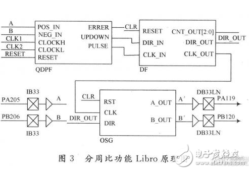
According to Figure 2, using the Libro 8.1 development platform of ACTEL Company, and using VHDL hardware language, the corresponding functional modules are created, and the schematic diagram is shown in Figure 3.

In Figure 3, PA205 and PB206 are the input pins of phase A and phase B of the original differential signal, respectively. After the signal is quadrupled by QDPF, the direction signal and pulse signal are output to the DF frequency division module. After frequency division by DF, the pulse and direction signals are output to the quadrature pulse generation module OSG, and the quadrature signal with phase is generated, and finally fed back to the CNC from PA119 and PB120.
The main modules are introduced separately below.
Quadruple frequency module QDPF: There are many quadruple frequency methods for quadrature signals, which are involved in many materials, and will not be introduced in detail here.
The frequency dividing module DF divides the frequency of the pulse sequence input to the CLK_IN pin according to the initialized and configured cycle ratio or the preset cycle ratio. The internal up and down counter counts the input pulses up (DIR_IN=1) or down (DIR_IN=0) according to the direction signal input to the DIR_IN pin, and outputs a pulse and a positive direction signal (DIR_OUT=1) when the up-count reaches the positive threshold. , counting down to the negative threshold is to output a pulse and a negative direction signal (DIR_OUT=0). If the count value is between the positive and negative thresholds, no matter the motor is reversed, or the threshold is shaken, that is, the direction changes repeatedly, the output direction signal remains unchanged. This is the key to the correct realization of frequency division. If this step is not handled properly, the motor may continuously send pulses to the CNC after positioning. Taking the frequency division by three as an example, that is, the counter counts up to 3 and then outputs a positive pulse (positive direction signal + pulse), and the counter counts down to -3 and outputs a negative pulse (negative direction signal + pulse). When the count value is (-3, 3), the counter only counts the pulses without outputting. The simulation result of QDPF is shown in Fig. 4.
After the OSG is triggered by the rising edge of the pulse signal, it jumps to the next state according to the current state and direction signal. When the direction signal is positive, the state is switched in the counterclockwise direction of the outer ring to generate a quadrature pulse sequence in which the A' phase leads the B' phase by 90°; when the direction signal is negative, the state is switched in the clockwise direction of the inner ring, A quadrature pulse sequence with the B' phase leading the A' phase by 90° is generated. The simulation is shown in 6.
In Fig. 6, dir is the direction signal, and its jumping edge is the place where the direction changes. It can be seen from Figure 6 that the sequence of the forward rotation of the motor is 10→11→01→00 (reverse)→01→11→10→…. The switching of the phase with the input signal is realized.
Finally, the overall structure of the cycle ratio function is simulated, and the input is an orthogonal pulse sequence. The input imitates the pulse output of the photoelectric encoder of the actual motor, and the pulse phase is switched repeatedly to verify the output after the motor is positioned. The simulation is shown in Figure 7. It can be seen from Figure 7 that when the input signals pula and pulp are continuously switched in phase, the output pula1 and pulp1 are divided by 3, and a new quadrature sequence is output after satisfying 3 or -3. The actual experimental waveform is shown in Figure 8.
In Fig. 8, waveform 1 and waveform 2 are the A-phase and B-phase quadrature pulses output by the photoelectric encoder, respectively. Waveform 3 and Waveform 4 are A'-phase and B'-phase quadrature pulses obtained by dividing the A-phase and B-phase quadrature pulses by 3, respectively. Observing Figure 7 and Figure 8, the results are consistent. The cycle ratio achieved with this scheme has been successfully applied to high-precision servo drives, and has been repeatedly verified in practical applications, and no errors have been found.
4 Conclusion
The realization method of the cycle ratio proposed in this paper can accurately divide the quadrature signal output by the photoelectric encoder according to the set cycle ratio. By setting the frequency division ratio, a frequency division of 1 to 256 times can be achieved, or even higher. In the actual system, you can also use the MCU to configure the cycle ratio online through the bus. If you want to achieve the weekly ratio of the fractional ratio, you only need to make a slight improvement on the basis of this scheme.
DN25MM digital magnetic flowmeter has long - term high measurement accuracy. Electromagnetic Flow Meter is actually unaffected by the physical properties of the fluid. The measurement accuracy can reach 1,0.5.
magnetic flow Meters have no mechanical or moving parts and usually do not require maintenance.
em flow meter is suitable for all liquid flow tests with conductivity greater than 5. The change of conductivity does not affect the change of performance.
The best integrated circuit in the world is used to eliminate the influence of excitation switch, and the compensation method of excitation current is used to achieve the optimal stability of the product.
Easy to operate, the flow meter is automatically set in the range of 0 ~ 10m /s, without changing the measuring range.
Electromagnetic Flow Meter,magnetic flow meter,electromagnetic water flow meter,em flow meter
Changshu Herun Import & Export Co.,Ltd , https://www.herunchina.com