Let's take a look at what LCD1602 means first? Liquid Crystal Display (LCD) means liquid crystal display, 1602 means 16 characters can be displayed in one line, there are two lines in total.
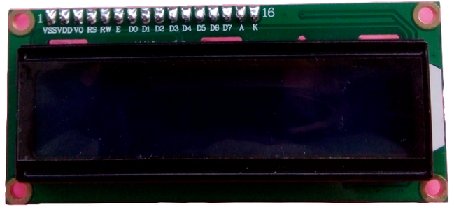
Now we take a look at how to use simple IO control and delay to realize the operation of LCD1602 LCD module. Since the LCD1602 is controlled by a single-chip microcomputer, based on the previous analysis, we must first figure out who is the controlled object and who is the controlled object. Obviously, LCD1602 is the controlled object, so let's start the analysis from LCD1602. The so-called control can also be understood as communication. For example, if you communicate with your roommate and hope that he will buy a bottle of green tea for you, then at least your roommate can understand your "instructions", know what green tea is, how to buy and so on . Okay, so how to communicate with LCD1602? Think about it, how do people communicate with each other? Say hello before communicating. For example, "Hello" and so on, you must say "Hello?" on the phone. After confirming that the communication is normal, the communication will start. Few people will start as soon as they call. "Wow", in case the signal is not connected after talking for a long time, it is not for nothing. In fact, the communication between the MCU and LCD1602 is also the same. The "Hello?" used in the phone is actually called initialization here. This "initialization" concept will often be encountered later. In fact, the device is also designed by humans, so the way of his work is, to some extent, human communication. After saying hello, you begin to enter the real theme. What theme? LCD1602 is a display module, the main function of course is to display. Since it is a display, we can think about it, there are nothing more than two things:
(1) What content do you want to display?
(2) Where do you plan to display it?
Obviously, these two contents are from the control of the single-chip microcomputer, and the single-chip microcomputer tells it to display what it displays (see electronics). This "show what" is the transmitted data. So how to transfer data to LCD1602 module? As mentioned earlier, LCD1602 represents 2 lines of 16 characters, which means there are different display locations. So how does the microcontroller tell the LCD1602 display location? Therefore, the previous analysis can be summarized into three questions, how to initialize; how to transmit the displayed content (what to display); where to display. How to answer these three questions? Of course you have to see the LCD1602 instruction manual.
In order to solve these three problems, let's first take a look at how people communicate. If you communicate in person, your signal (voice) can be directly transmitted to the other party, and the other party can understand it. If they are far apart, use communication tools such as telephones. The former signal transmission carrier is air, and the latter is telephone line. So let's take a look at what the signal transmission carrier of MCU and LCD1602 is like, and we need to check the schematic diagram.
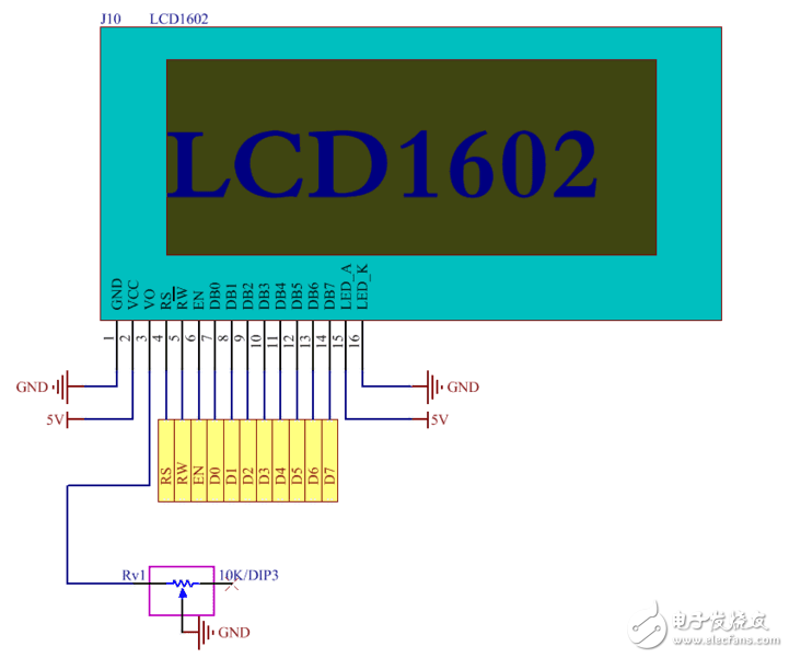
As shown in Figure 3-1, LCD1602 has a total of 16 pins, among which pins 1, 2, 15, 16 are related to the power supply and we will ignore them. In addition, pin 3 is connected to the adjustable resistor Rv1, which is used to adjust the backlight of the liquid crystal module, which is also ignored here. What we are concerned about is the pins related to signal transmission, which are obviously related to pins 4 to 14. From the figure, we can see that the single-chip microcomputer is connected to RS, RW, and EN through P4.1, P4.4, and P4.5, and the P2 port is connected to D0 to D7, a total of 10 wires. In other words, all instructions and data of the single-chip microcomputer are completed through these 10 wires. How to control LCD? Of course, read the instruction manual of LCD. Here is an analogy. A person in the room stipulates that he knocks on the door three times, and the person in the room opens the door. If you want to enter the house, you have to knock three times. If you don't know this rule, knock four times, or yell, the door will not open. What does it mean here? When you want to communicate with a device, you must strictly follow the rules of the device. For example, a German can only speak German. If you want to communicate with him, then you can only speak German with him. If you speak Chinese and he speaks German, this is messy and the information cannot be transmitted (). At this time, you can choose to communicate with Germans who can speak Chinese, that is, to change the communication partner. Similarly, if you think a certain device is too troublesome to operate, then you can replace it with another device that has the same function and can meet your requirements. However, once you have selected a device, you must 100% follow the "rules for the use of this device" to operate. Different peripheral devices have different rules, which means that these rules are diverse. Going back to the example of opening the door mentioned earlier, it can also be designed like this, for example, a total of two knocks, the first one should be a little harder, and the second one should be a little lighter. Or tap it three times, tap it once, etc. But for us, we don't need to ask why, just do it. How to design rules is something that engineers who design this device or module should think about. I believe that the design of these rules must have their reasons. But we only think about the problem from the application level, no matter what you stipulate, I will just do it. Where are these rules? Check the chip manual or official instructions. There is so much wordy, in fact, to emphasize that learning this technology must be based on the chip manual (official information), and will continue to be emphasized later. In fact, LCD1602 includes other modules mentioned later, the same is true. If you want to communicate with it, of course you must follow its rules. Below we will interpret its rules to solve the three problems mentioned earlier, initialization, content display, and address display.
(2) LCD1602 initializationRegarding this point, the LCD1602 instruction manual has clearly told us, don't think about it, don't care what you mean, just do it.
Delay 15ms
Write instruction 38H
Delay 5ms
Write instruction 38H
Write command 08H
Write command 01H
Write instruction 06H
Write command 0CH
The above is the initialization process, the delay part is easy to solve, as I have mentioned before. Here is how to "write instructions". The question is, how does the LCD module know whether the MCU is giving me commands or data? (3 Discuss Electronics) When LCD1602 sees RS is high, it understands, oh, you want to send me data; when it sees RS is low, you know you want to give me instructions. This is just the choice of "command" or "data". There is another problem. Our purpose is to "write instructions", so how does the LCD module know whether it is "write" or "read"? Let's look at the RW signal again. When RW is low, the LCD module will know, and the MCU will "write" for me; when RW is high, the LCD module will know and the MCU will "read". Obviously, we need to set RW to low here. Both "write/read" and "command/data" know how to tell the LCD module, then how did this command pass? It is transmitted through the 8 lines D0-D7 (that is, the P2 port). For example, the command I want to transmit is x033, then put this data 0x33 to the P2 port, when LCD1602 sees "write" and "command" , You know to take the 0x33 instruction on the P2 port. In this way, the purpose of "write" "command" "0x33" is achieved.
But not this way, the LCD1602 can be executed normally. no. Going back to the example we mentioned earlier, here is a condition. After hearing three knocks on the door, the person in the house judged that the code was correct, but did not open the door directly. Instead, he notified his superior and only opened the door after obtaining authorization from the superior. . That is to say, two conditions are correct and authorized by superiors. The same is true for LCD1602. The command is not executed immediately after receiving the command, and it has to wait for another signal, which is the EN enable signal. At this time, EN gives a pulse of a certain width, and LCD1602 starts to execute.
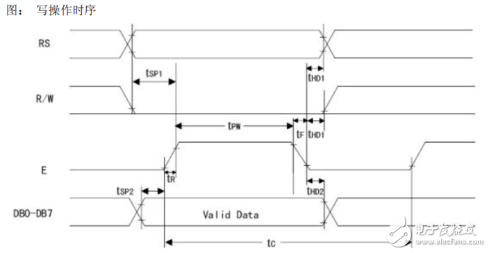
In this way, it is easy to write the code for writing instructions based on the previous analysis:
void Lcd_Write_Cmd (unsigned char Cmd) {
delayMs(5);//Note that a delay of 5ms is needed to compare insurance instead of judging the busy signal
RW = 0;
P2 = Cmd; //Ready instructions
RS=0; //Tell LCD1602 that P0 puts commands instead of data
EN=1;
delayUs(5); //According to the timing diagram, the pulse must have a certain width
EN=0; //Make the instruction valid and start execution
}
In the same way, in the above code, just change the RS signal to 1, which is the code for writing data.
voidLcd_Write_Data(unsignedcharmData) {
RW = 0;
delayMs(5);//Note that a delay of 5ms is needed to compare insurance instead of judging the busy signal
P2=mData;//Ready instructions
RS=1;//Tell LCD1602 that the data in P0 is not a command
EN=1;
delayUs(5);//According to the timing diagram, the pulse must have a certain width
EN=0;//Make the instruction valid and start execution
}
Speaking of this, the LCD1602 initialization code should be able to be written. At the same time, we have also written the code to pass the instruction, so now we only need to know the content of the instruction.
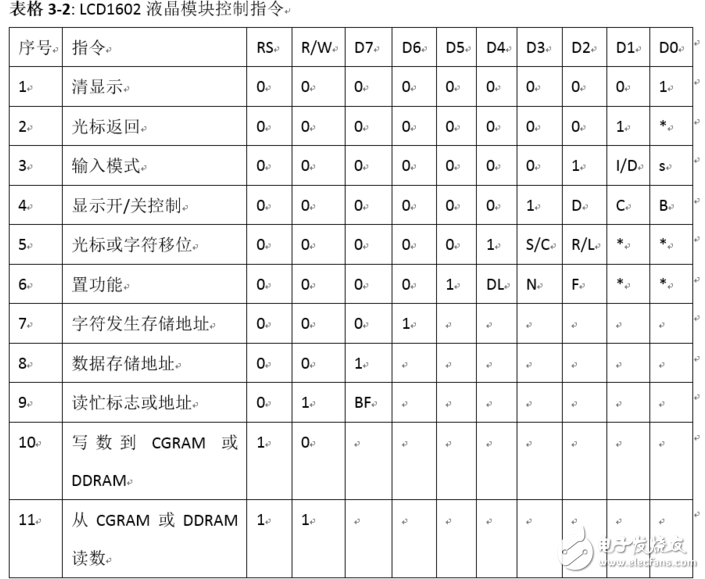
Instruction 1: Clear display, instruction code 01H, and reset the cursor to address 00H.
Command 2: The cursor is reset, and the cursor returns to address 00H.
Instruction 3: Cursor and display mode setting I/D: Cursor moving direction, high level move right, low level move left S: whether all text on the screen moves left or right. High level means valid, low level is invalid.
Command 4: Display switch control. D: Control the on and off of the overall display, high level means open display, low level means off display C: control the on and off of the cursor, high level means there is a cursor, low level means no cursor B: whether to control the cursor Flashing, high level flashes, low level does not flash.
Instruction 5: Cursor or display shift S/C: Move the displayed text at high level, and move the cursor at low level.
Instruction 6: Function setting command DL: 4-bit bus at high level, 8-bit bus at low level N: Single line display at low level, double line display at high level F: Display 5x7 dot matrix characters at low level, Displays 5x10 dot matrix characters at high level.
Command 7: Character generator RAM address setting.
Command 8: DDRAM address setting.
Command 9: Read busy signal and cursor address BF: It is a busy flag bit, high level means busy, at this time the module cannot receive commands or data, if it is low level means not busy.
Command 10: Write data.
Command 11: Read data.
So what instructions you need to give LCD1602, just pass to the Cmd parameter in the void write_com (unsigned char Cmd) function.
(3) LCD1602 determines the display positionNow we come to solve the second question mentioned above: "Where to display?" That is, how are the 32 spaces of the LCD module determined.
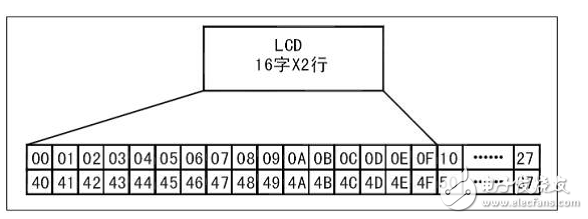
As you can see from the above figure, there are two lines, 00 to 0F and 40 to 4F exactly corresponding to the 32 spaces of LCD1602. It can be seen that the display position of the liquid crystal module is determined by the code value corresponding to this table. For example, the address of the first character in the second line is 40H, then its address is 40H. Note that the 8th data storage address in Table 3-2, D7 has been written dead. The final display address should be 40H+10000000B (40H+80H), so we only need to pass this value to Cmd so that LCD1602 knows that it is displayed in the first position of the second line.
(4) LCD1602 confirms the display contentAs mentioned earlier, if the data is transmitted, it is the content to be displayed. For example, if I want to display the letter A, how do I do it?
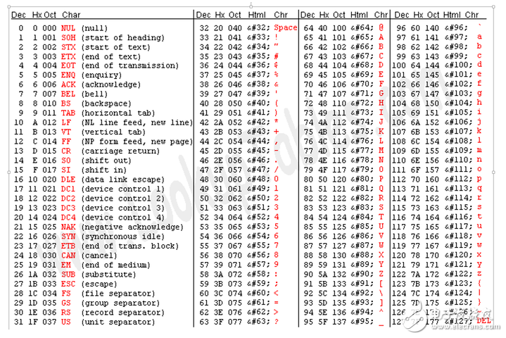
As you can see in the above figure, if you want to display A, the high bit of the data is 0100, and the low bit is 0001, so it is 01000001. Send this data to LCD1602, it knows to display A.
In this way, the three problems are solved, "initialization", "write instruction", and "write data".
Now look back and see what knowledge of the single-chip microcomputer we have used in the process of using the single-chip microcomputer to control the LCD1602. Go back and look at Figure 1, 10 connecting lines, P4.1, P4.4 and P4.5, plus P2 port, mainly through the changes of P4.1, P4.4 and P4.5 to send commands or data , P2 port changes reflect the content of instructions or data. It can be seen that we only used IO port control and delay in this process. The other long part is used to understand the 1602 usage rules. Note that this is a rule of use, not the principle. For example, when you send a clear screen command to LCD1602, do you understand how LCD1602 receives this command to clear the screen? I don't know, and there is no need to know. The LCD module manual does not tell you either. For example, when you use a mobile phone, you click an application to open it, and then use it according to its rules, such as listening to songs, surfing the Internet, etc. You don't need to care about how they are implemented. In fact, the mobile phone is also a module, we only need to learn to operate it, no matter what happens in it.
(5) SummaryNow let's summarize the content of the above analysis. The role of the LCD1602 liquid crystal module is to display. Since it is a "display", it is nothing more than what to display and where to display. So how to determine what is displayed? Determined by the ASCII code table. How to determine the location of the display? Use Table 3-3 to determine. When the single-chip microcomputer controls the LCD1602 liquid crystal module, that is, when the two objects communicate, you must first "greet", that is, initialize. How to initialize it? The specific steps are already given in the instruction manual, just copy it. After clarifying this idea, the rest is to implement each step. It involves how to write instructions, write data and how to read busy signals. Check the timing diagram for details.
What features you consider more when you choose an university laptop for project? Performance, portability, screen quality, rich slots with rj45, large battery, or others? There are many options on laptop for university students according application scenarios. If prefer 14inch 11th with rj45, you can take this recommended laptop for university. If like bigger screen, can take 15.6 inch 10th or 11th laptop for uni; if performance focused, jus choose 16.1 inch gtx 1650 4gb graphic laptop,etc. Of course, 15.6 inch good laptops for university students with 4th or 6th is also wonderful choice if only need for course works or entertainments.
There are many options if you do university laptop deals, just share parameters levels and price levels prefer, then will send matched details with price for you.
Other Education Laptop also available, from elementary 14 inch or 10.1 inch celeron laptop to 4gb gtx graphic laptop. You can just call us and share basic configuration interest, then right details provided immediately.
University Laptop,Laptop For University Students,University Laptop Deals,Recommended Laptop For University,Laptop For Uni
Henan Shuyi Electronics Co., Ltd. , https://www.shuyioemelectronics.com