In modern production, in order to ensure the safe and reliable operation of mechanical equipment, it is usually necessary to adopt appropriate instruments and meters, use fault diagnosis technology to find faults in time, and take reasonable maintenance or protective measures to eliminate faults, prevent and avoid accidents. Based on the consideration of instrument size, portability and ease of operation, a large number of instruments and equipment in industrial fields such as coal, steel, metallurgy, electric power, and chemical industries have gradually adopted touch screens as the input devices of the system.
In response to this situation, the author studied the touch screen input interface during the development of a smart instrument for mechanical fault diagnosis. Designed the interface circuit between the four-wire resistive touch screen and the PXA255 processor, analyzed the design principle of the character device driver under the Linux framework, completed the development of the interface driver for the touch screen, and designed the MiniGU I user program with the touch screen as the input device . The touch screen is used as the input device of the instrument, and the human-computer interaction is straightforward, which greatly facilitates the use of on-site operators.
1 Hardware structure and working principleAccording to different working principles and transmission media, touch screens are mainly divided into resistive, capacitive, infrared, and surface acoustic wave types. The resistive touch screen is a 4-layer transparent composite film screen, as shown in Figure 1. The bottom is a base layer made of glass or plexiglass; the top is a plastic layer whose outer surface is hardened to make it smooth and scratch-resistant; in the middle are two metal conductive layers, and there are many small transparent isolation points between the conductive layers. Separate. The two metal conductive layers are the working surface of the touch screen, and both ends of which are coated with a silver glue, which are called a pair of electrodes on the working surface of the touch screen. The X working surface and Y working surface of the four-wire touch screen are respectively added to two conductive layers, and there are a total of 4 lead wires connected to the X electrode pair and the Y electrode pair of the touch screen. When the stylus touches the screen, the two conductive layers touch at the contact point. When a resistive touch screen is used as an input device in conjunction with a display screen, the essence of its work is to determine the contact coordinates of the touch screen by measuring the partial pressure of the resistance in the X and Y directions, and map the coordinates to the display screen coordinates. Realize human-computer interaction. Because the working surface of the resistive touch screen is completely isolated from the outside world and is less affected by the environment, it has the advantages of not being afraid of dust and water vapor, high stability, and no drift, which is especially suitable for industrial field use.
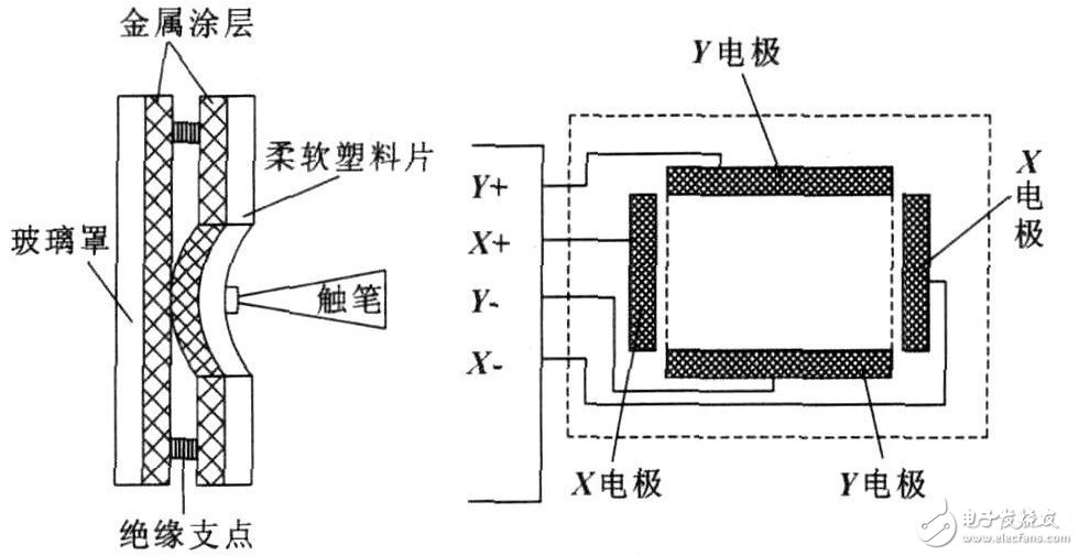
Figure 1 Resistive touch screen structure
In the design process, ADS7843 is selected as the AD conversion chip of the touch screen interface. It has a 12-bit conversion accuracy and supports a 4 096 × 4 096 dot matrix LCD to meet the design requirements of the instrument.
The instrument system processor selects the Intel Xscale architecture PXA255 processor, and uses its GPIO port to simulate the SPI interface to communicate with ads7843. The interface principle is shown in Figure 2. The ADS7843 completes the switching of the acquisition channel and the acquisition of the voltage at the contact point. Its operation sequence is mainly composed of control word input, voltage acquisition and analog-to-digital conversion, see references for details. As long as the control word is sent to the D IN port according to the timing requirements in the driver, the acquisition result of the corresponding channel can be obtained from DOUT.
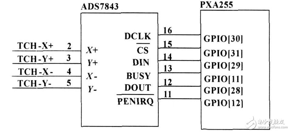
Figure 2 Interface circuit between ADS7843 and PXA255
2 Touch screen interface driverThe Linux driver is a part of the system kernel. It separates the software and hardware, and provides the communication interface for the application program to access the hardware, and manages and protects the system hardware downward. The touch screen is defined as a character device under Linux, and its driver mainly completes the collection of the contact voltage, and transmits the X coordinate, Y coordinate and pen motion (press, lift or drag) data to the user space. When the stylus is pressed, pin 11 of ADS7843 outputs a low level, triggering pin 12 of the PXA255 general-purpose IO port to generate an external interrupt, start the timer, and realize the action of the touch screen. The driving process of the touch screen is shown in Figure 3.
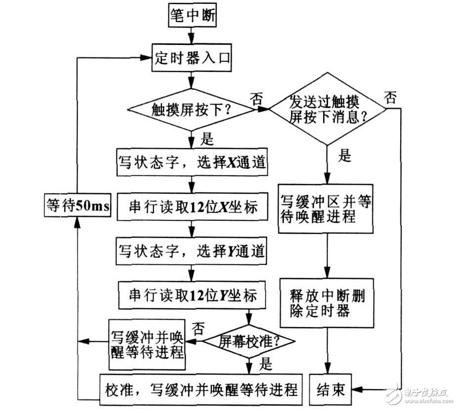
Figure 3 Touch screen driver structure flow
2.1 Drive writing
The touch screen driver is a character device driver under the Linux framework.
The entry function of the driver is ads7843_ts_init (). In this function, the I/O port is initialized, the pen interrupt and the device node are registered, and the initialization of the device file system to create a standard character device is completed [8-10]. The structure of touch screen device operation is defined by ads7843_ts_fop s.
staTIc struct file_operaTIons ads7843_ts_fop s = {
read: ads7843_ts_read,
poll: ads7843_ts_poll,
ioctl: ads7843_ts_ioctl,
fasync: ads7843_ts_fasync,
open: ads7843_ts_open,
release: ads7843_ts_release,
};
In this way, the development of the device driver can be completed only by correctly defining several function processes in the structure according to actual needs.
When the touch screen device is opened, first execute the ads7843_ts_open () function, and in this function, initialize a buffer area for storing coordinate data. After the touch screen is pressed, the system first triggers an interrupt. In the ads7843_ts_interrup t () interrupt program, the status of the in_TImehandle global variable is judged. The in_TImehandle is changed in the timer function, that is, after the interrupt is entered, the timer delay is passed. At 20ms, complete the software debounce of the touch screen, and then judge whether the touch screen is pressed. Then switch to the X and Y channels through the read_xy () function, complete the AD conversion of the contact voltage, and read the 12-bit coordinate value.
static void ads7843_ ts_ interrup t (int irq, void 3 dev_ id,
struct p t_regs3 regs)
{
sp in_lock_irq (&tsdevlock);
if (in_timehandle "0)
{
sp in_unlock_irq (&tsdevlock);
return;
}
disable_irq (IRQ_GPIO_ADS7843);
ads7843_ts_starttimer ();
sp in_unlock_irq (&tsdevlock);
}
When the application calls the read () function, it enters the ads7843_ts_read () interface function of the driver. Obtain the sampling result in this interface function, determine whether to calibrate the coordinates, write the final result into the buffer, and copy it from the kernel space to the user space through the copy_to_user() function, so that the application can use it. A non-blocking operation is used in the ads7843_ts_read() function, so that it returns immediately when no data arrives, and then asynchronously triggers fasync() to notify the arrival of the data. The ads7843 _ ts_poll () function is used for non-blocking operation of the driver, and the ads7843_ts_fasync () function is used to drive asynchronous triggering. The ads7843_ts_ioctl () function provides parameters that can be controlled from the user mode, such as whether the touch screen is calibrated in the drive, the maximum and minimum coordinates of the screen, etc. The ads7843_ts_release() function is used to close the touch screen device.
2.2 Calibration of touch screen
In the instrument development process, the touch screen is used as an input device in conjunction with the LCD. In order to make the coordinates sampled from the touch screen correspond to the display coordinates of the screen, a mapping is needed, that is, the touch screen needs to be calibrated. As shown in Figure 4, the touch screen and LCD screen used are all standard rectangles. As long as the installation is reasonable, it can be considered that the X-direction coordinates of the touch screen are only related to the X direction of the display screen, and the Y-direction coordinates are only related to the Y direction of the display screen. Assuming that the resolution of the display screen is W×H, the sampling coordinates of the touch screen corresponding to the upper left corner of the display area are (x1, y1), and the coordinates corresponding to the lower right corner are (x2, y2), then the sampling coordinates of any point on the touch screen (x, y) The corresponding relationship with the display coordinates (xd, yd) can be calculated according to the following formula:

In this way, after measuring the sampling values ​​of (x1, y1) and (x2, y2) points on the touch screen, use the above formula to compile the calibration function. During the operation of the touch screen, the display coordinates corresponding to the actual touch points are calculated to complete the touch screen calibration.
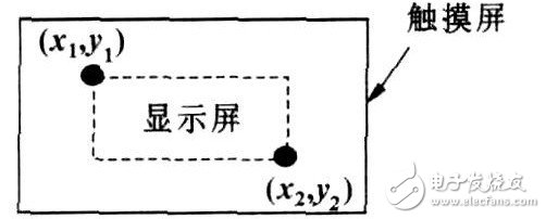
Figure 4 Calibration of touch screen
3 Touch screen user applicationThe created Linux device file system touch screen node is /dev/ts. In the application, you can use the open function to open the device file like a file, and then use the read () function to read the data passed by the driver to the user space. The instrument application program is developed using MiniGU I. MiniGU I is a lightweight graphical user interface support system developed by Beijing Feynman, which can be used in real-time embedded systems. Its function interface is similar to the Windows SDK, which is convenient for development.
MiniGU I's Input Abstract Layer (IAL: Input Abstract Layer) provides rich support for touch screen, mouse and other input devices, and supports PXA255 processor platform. You can use the touch screen in the application after simple settings. When configuring and installing MiniGU I, use the 22enable2px255bial item. Because the static compilation method of embedded resources is used when installing MiniGU I, before compiling, you need to create the mgetc2pxa1c file in the src / sysres/ directory of MiniGU I and use it in it The following sentence sets the system parameters and sets the touch screen as an input device.
static char * SYSTEM_VALUES [] = {"fbcon","PX255B","/dev/ts","none"};
Figure 5 shows how MiniGU I processes the touch screen input.
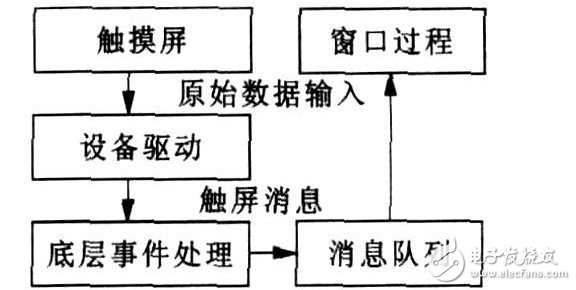
Figure 5 Touch screen input in MiniGU I
MiniGU I receives the original input data through the touch screen device driver and converts it into MiniGU I abstract touch screen events and data.
Related low-level event processing routines convert these touch events into upper-level touch messages and put them in the corresponding message queue. The application obtains these messages through the message loop, and hands them to the window procedure for processing. When compiling an application for the touch screen, all you need to do is to call the corresponding statement to complete the expected operation when the window receives a touch screen message such as MSG _LBUTTONDOWN.
4 ConclusionThe embedded intelligent instrument touch screen interface enhances the human-computer interaction function of the instrument system, and facilitates the use of the operator; the modularization of the interface circuit and driver program facilitates the subsequent improvement of the instrument and the development of new products, and can be transplanted and applied as needed Various occasions. The designed touch screen interface has been successfully applied to the fault diagnosis and inspection instrument, its work is stable, the operation is reliable, and it has good practical value.
Suizhou simi intelligent technology development co., LTD , https://www.msmsmart.com